This is a subdesign of a much larger project. This board serves as an inertial measurement sensor that measures the specific force (acceleration) on two axes as well as the rate [of rotation] around the axis that stands perpendicular on the axes for measuring acceleration.
That’s the reason for calling this thing a Plane Sensor.
At least three such plane sensors covering three independent planes in space are required in order to construct a complete inertial measurement unit (IMU) for three-dimensional space.
Usually one tries to make such a complete IMU as small as possible and mount it as close as possible to the center of mass of the object under measurement. (Note: From a mathematical point of view it could be placed anywhere, but the closer it is located at the center of mass the better it is especially for measuring the specific force.)
In the targeted application it is planned to distribute multiple plane sensors equally around the nominal center of mass in a special pattern.
A few Hardware Features:
Sensor Issues:
- Silicon Sensing MEMS CRS03 gyroscope (10Hz bandwidth, +/- 100 degrees/s)
- Gyroscope output is sampled by an Analog Devices AD7707 16Bit Sigma-Delta ADC (output rate is 100Hz)
- Analog Devices ADXL2XX series and Memsic MXD20XX series dual-axis accelerometers (various ranges available such as +/- 5 or 10g, resolution around 2 – 5 mg). Only one accelerometer can be selected at a time (via software)
Both accelerometers were put on this first revision for evaluating which one is more suitable. - both accelerometers provide duty-cycle modulated digital outputs that are decoded by a micro controller; data rate is 100Hz
- the accelerometer outputs are decoded into 16 bit samples (although the actual resolution of the selected devices is around 12 bits)
- a total of three temperature sensors; one inside the Memsic accelerometer (very important) and two external National Semiconductor LM35-series sensors;
all intended for temperature compensation - temperature sensors are sampled by 8Bit ADC of the micro controller at a rate of 2Hz (analog signal conditioning provides a resolution of exactly 0.5 degrees centigrade)
Various Stuff:
- the used micro controller is a Microchip PIC16LF74 or PIC16LF77 running at 8MHz (2MHz instruction rate);
decision for PIC rather than AVR was made primarily due to lower power consumption - separate power supplies for gyroscope, accelerometers, digital stuff (micro controller plus some additional logic) and IO drivers for optimal noise suppression and high reliability
- nominally 6V power supply via data transmission cable;
6V was selected in order to be able to generate clean 5V analog supply voltages for the gyroscope and the accelerometers by linear regulators - 4-Layer PCB with appropriate ground plane splitting for analog sections
- PCB size is 69mm x 44mm
Data Transmission:
- electrical level is RS-485 (differential signaling for high reliability)
- Maxim ESD-hardened E-series slew-rate limited transceivers
- reduced slew-rate eliminates the need for RS-485 termination and reduces electromagnetic emissions
- placeholders for termination resistors are provided, just for the case …
- additional (optional) transzorb protection for differential lines
- standard asynchronous data transmission is used nominally, but can be virtually reconfigured by software to all 2-signal transmission modes provided by the PIC USART
- additional (optional) third signal pair for sideband signaling (currently not used)
- currently the sensor board does not need to receive anything and two of three RS-485 transceivers have not yet been mounted (see pictures below)
- nominally 250kBAUD transmission rate
- each transmitted byte contains 4 bits of actual data; the rest is used for redundant frame signaling and parity bits for forward error correction of single-bit errors
- neat ITT Cannon MDSM series 9 position micro sub-d connector
Performance Characteristics: These parameters are to be determined as of now (May 29th 2003). The most important parameter will be the drift of the complete IMU system. That is, how much the measured position has changed (by integrating the accelerometer readings) within a certain time although no movement has been performed, or to which extend the attitude has changed (by inegrating the gyroscope readings) although there have been made no rotations.
Another thing is drift under dynamic conditions that includes things like frequency response of the sensors etc. That’s a little bit difficult to determine in practice, because one needs special mechanical test equipment in order to generate deterministic mechanical motions.
What has been observed so far from the digital sample streams is a precision of around 12 bits for both gyroscope and accelerometer under static conditions. The lower 4 bits appear to be just white noise.
Further Development:
The next step is to calibrate the sensors appropriately and to perform some basic performance testing with some sort of 2-D IMU software in order to determine parameters like drift.
Then a couple of twins (at least two, but very likely three more) will have to be made with almost no change in architecture and sensor types. They will be used in their targeted application test bed for higher-level evaluation and testing porposes.
It is planned to do a redesign of these plane sensors some day with state-of-the-art technology in order to make them smaller, lighter, and better. This counts especially for the gyroscope, which is a rather fat and heavy thing that eats a lot of current (around 50mA). Although there are already better gyroscopes available today (e.g. the ADXRS150 from Analog Devices), the decision was made to go with the current setup in order to get something working in hand.
Some Pictures:
Perspective View
Top Side View
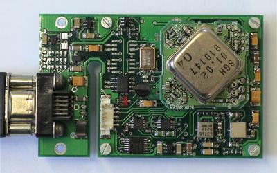
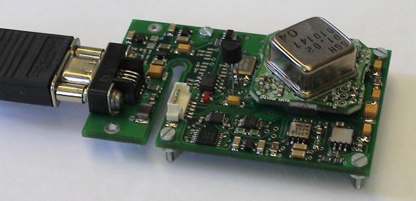
shows most of the important devices such as the gyroscope (the big one), the accelerometers (down right), one temperature sensor (in the middle of the picture; this is to be mounted somehow at the gyroscope case later), the connector with attached plug to the left, a connector for micro controller programming (white)
Bottom Side View
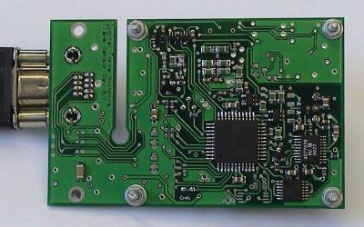
shows the PIC micro controller the AD7707 and lots of small stuff primarily for signal conditioning of temperature sensors
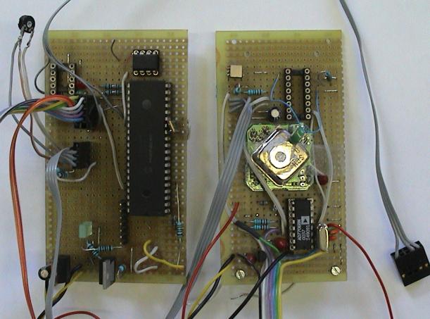
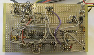
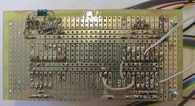
Some historical Pictures of the Prototype for some basic Testing
