Over a period of approx. 2 years there have been created various technologies that were needed in order to produce that movie:
The following article is stepping through various aspects of that project and is giving some closer insights about how this has been done and what is needed to accomplish that.
The basic Goal
There had been made a decision to participate in a sailing race from the most southern part of the Baltic Sea (Wismar/Germany) to the most northern part of the Baltic Sea (Töre/Sweden) – a course of approx. 900 nautical miles or 1600km. This race is named “MidsummerSail” organized by Robert Nowatzki. Also refer to the web site of the race: https://www.midsummersail.com Since just participating at that race would be perhaps a bit too trivial (no, it is not!) there was the idea to produce a time lapse over the course. So there could be placed a camera at the back of the sailing vessel that is taking pictures in a regular period. So the aim was to create something special here that has not been done before. At a first glance, one might think that this can be easily accomplished by placing a small action cam there. However, it is not (not really). There are several aspects. Some of them are:
- scrappy image quality, especially during night time
- suboptimal automatic exposure of existing cameras
- a camera fixed to the boat is not good, since the horizon is not stable
- the system has to function absolutely autonomous and stable over 1-2 weeks
- vast amounts of storage capacity is required for the pictures
So there had to be deployed some other technologies….
Camera and Lens
There has been used a system camera with a full-frame (35mm) sensor. As lens a 14mm one has been chosen with F-stop down to 1.8. This is a rather remarkable performance for such an ultra-wideangle lens. However, this has been an important point here since the system should also deliver acceptable pictures during night time. The use of such an ultra-wideangle lens is important as well here, because it does convey the viewer the impression that he/she is sitting at the back of the boat, watching the activities.
Although this is cutting away approx. one F-stop, there has been also used a fixed polarization filter. The intention of that filter was to deal with expected heavy reflections of the sunlight in the water. Though, in the end it is not quite clear whether this filter did improve the overall quality.
Camera Mounting
It was clear from the beginning that the camera would have to be mounted to a gimbal system which is always keeping the camera at level with the horizon. The next problem to solve is the question how the gimbal can be attached to the vessel. At the stern of the boat there has been already present a truss for carrying a larger solar panel. This has been found as a good base for the attachment of additional truss structures carrying the gimbal and hence the camera.
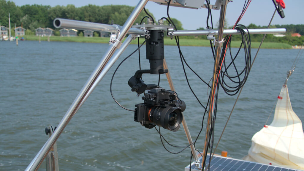
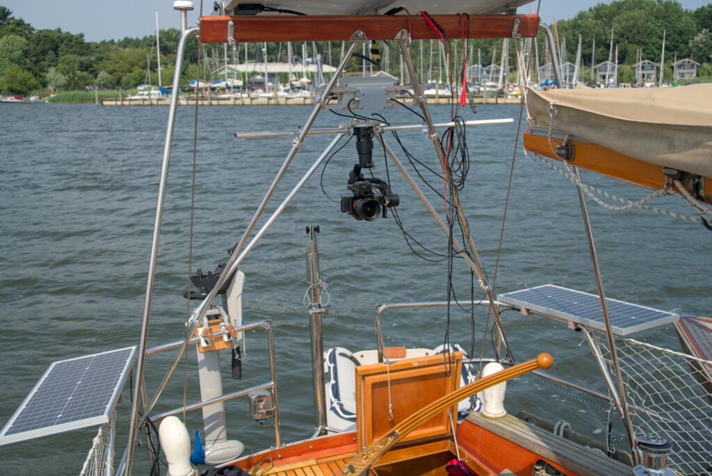
The pictures do also show an electronics platform above of the gimbal mounting, whereas the smaller grey box is a voltage regulator solely for the gimbal. These pictures are from an earlier experimental stage and the voltage regulator has been replaced later on.
Hardening of Electronics and Mechanics against harsh Environment
It is necessary to protect the equipment from water ingress – let it be rain or splashing sea water. A little bit challenging here is the freedom of movement the gimbal is needing. To do so, there has been decided to make some sort of coat or jacket that is being put around the equipment – with a cut where only the lens is exposed to the outside. Latex rubber has been chosen as base material here since it is rather simple to make such a “cloth” from it (in contrast to silicone, which is virtually impossible to glue).
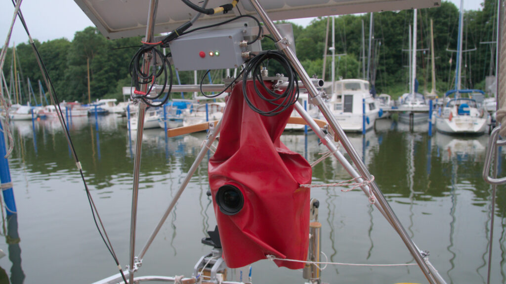
The coat is open at the bottom to allow venting and avoid collection of condensing water or any other water that might have entered the system through leaks. At the top, sealed cables are fed into the system so that everything is formally water-tight from the top. The coat is pulled gently with some cords to the outside, hence giving the gimbal more freedom to move.
It should be noted that this protection mechanism – although it did work in the targeted environment for a few weeks – is not the way to go for more demanding environments. There’s also an issue with latex rubber and ultraviolet light coming from the sun. A glass dome made of high-quality glass without any major optical distortions where the complete gimbal including the camera fits would be the way to go here. However, this would be certainly extremely expensive at that scale and it is not clear whether this is existing these days at all.
Camera Control Computer
The camera needs to be controlled from an external computer through USB. A RaspberryPi model 4B has been chosen here. This computer is also enclosed within a sealed box placed close to the gimbal (hardly visible in the picture above behind the prominent grey box). Also located within that box is a large NVMe SSD with a capacity of 4TB. It should be noted that this SSD has been connected to the RaspberryPi in a rather low-performance fashion through a simpler USB-NVMe adapter and also just via one of the USB 2.0 ports. The reason for that is power saving….
There have been also applied some downclocking-measures for the RaspberryPi in order to limit its power consumption to only what is really needed.
This camera control computer is also connected through WiFi (the watertight metal enclosure feeds out an according antenna) with the primary board computer of the vessel which is important for system monitoring as well as for various other telemetry data.
In order to use the RaspberryPi 4B there had to be made some small tweaks allowing the attachment of an external WiFi antenna as well as lifting the power limit for the USB ports. Refer also to these remarks here.
Electrical Power Supply
Essentially, the system is being powered from the 12V main power bus of the vessel. However, for the sake of high reliability there has been decided to include a battery-backed UPS (uninterruptible power supply) so that the system does not immediately fail in case there are external power-outages. This system is providing power to both gimbal and camera as well as the control computer. This is based on a system called OpenUPS and is using two 3S 2600mAh LiPo packs is series (totaling 22.2V@2.6Ah or 50-60Wh of energy). All these things are housed in the grey box with those two LEDs which is prominently visible in the picture above.
The power consumption of the whole system including camera, gimbal, and computer has been measured to be around 15W (of course excluding major forces acting on the gimbal). This is not that much, but this has been the largest sink of energy aboard over the time. For the total time of almost 9 days the race took, this sums up to approx. 3.2kWh.
So all in all this battery backup is giving a time of 3-4 hours of autonomous operation. In fact, this has not been needed over the course of the race. However, due to other difficulties with the power system aboard this battery-backing was worthwhile resp. did pay out, because it did allow to dynamically attach it to alternative power sources.
Control of the Camera and automatic Exposure Setting
There had to be made a special software that is doing the following:
- Permanently ensure that the camera is set up with an exposure setting that is delivering the best possible picture.
- Collect telemetry data from the primary board computer (especially positioning information, but also other stuff like velocity of the vessel or water depth).
- Take pictures within a regular period and store it together with auxiliary data on the SSD.
As for the telemetry data there is existing a system named SignalK (refer to https://signalk.org) which was already running per default on the primary computer of the vessel and is intended to collect and distribute various information. So the software that is caring about taking the pictures for the time lapse connects to that SignalK server and continuously grabs data from there.
For the communication with the camera via USB there has been used gPhoto2 (http://www.gphoto.org). gPhoto2 can be used for all the needed actions such as adjusting exposure parameters, grabbing preview-pictures, taking the actual picture and grabbing the picture finally. However, there have been detected intermittent hangups of the gPhoto2 library which have posed a critical risk in wake of the required autonomous operation over many days or even weeks. In order to cope with that situation there has been developed a separate server (by means of a piece of software) that is exclusively dealing with the gPhoto2- resp. camera-communication. In case that server is hanging up, it is being automatically killed and restarted by the primary software. Although this can lead to loss of pictures nonetheless when a problem appears at the wrong moment, this is significantly improving the situation. In fact, only 18 pictures (of approx. 80000) have been lost that way over the complete race.
The autoexposure system is a complex matter as such and cannot be described in detail here. The usual camera has got an automatic exposure system. However, it could not be used here because of various limitations. Two of them:
- In case of the particular camera that has been used, it was not possible to limit the exposure times. This would have caused unusable pictures during night time when the camera starts to make use of excessively long exposure times.
- Typical autoexposure mechanisms tend to fail when taking pictures against a very bright background – not so speak about taking the picture directly against the sun. The result is usually a rather dark and unusable foreground for the sake of a not-so-overexposed background. All in all this is anyway a compromise that has to be taken because of physical limits of the dynamic range of the camera. However, in the particular case it would be clear from the very beginning that there will be such situations taking pictures directly into the sun. So the system would have to be prepared for that accordingly.
So the autoexposure mechanism that has been implemented here is taking care about both a typical histogram-based control where the system attempts to adjust the exposure in a way where there is a possibly equally-distributed histogram with similar portions of underexposed and overexposed pixels, as well as what I call a “scene-based” autoexposure mechanism that is tolerating a certain amount of overexposed or underexposed areas (not pixels!) in the picture.
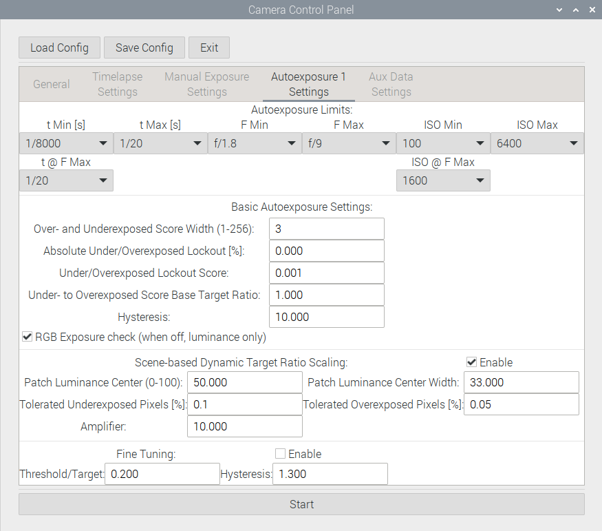
The following picture is showing an exemplary view of some sort of rudimentary control screen of the application controlling the time lapse and autoexposure. Notice that this is not an original screen shot but generated later for purposes of illustration, as the telemetry data shown in the bottom/right area is missing.
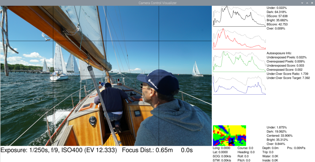
There can be seen histograms for both luminosity-only as well as RGB channels. Below the histograms there can also be seen a rectangle of colored patches, which is representing the actual picture divided into patches consisting of a larger amount of pixels which are classified into whether they are to be considered as underexposed (black), rather dark (blue), quite ok (green), rather bright (yellow), or overexposed (red). There is also shown a percentage of each class of patch. So based on that information the system resp. the implemented heuristic algorithm can decide on a broader scale whether it is worth to allow more underexposed or more overexposed pixels.
The algorithm itself is out-of-scope here. This is just a screenshot of the various parameters that can be set here:
It should be noted that there have also been made experiments using a neural network resp. artificial intelligence in order to implement an autoexposure mechanism. Thereby the luminosity histogram has been fed into a neural network consisting of a few layers of neurons. The results of such a quick&dirty test after a training with a few test pictures were remarkably good. For the actual implementation this has not been used, however, since there was no time to qualify resp. test this deeply. Though, this might be a matter to pick up again in future, possibly also adding such a scene-based evaluation into the decision. However the point with such AI systems is always that they require vast amounts of processing power for possibly simple tasks….
Collecting Pictures and other Data, finally
So the system has been set up to take one picture once every 10 seconds. The pictures have been stored essentially in 4K resolution in both RAW and Jpeg format, while the latter has been intended just for preview-tasks. Over the course of these almost 9 days it took for the race this makes around 80000 pictures. As mentioned earlier, 18 pictures have been lost in total. The size of a RAW image is approx. 12MiB – not that big because “only” 4K resolution. However, in sum this is around one terabyte for all the pictures.
Along with the pictures there has been stored some sort of extra-EXIF information in form of Json-files. For instance the according file associated with the picture in the screenshot above is containing the following information:
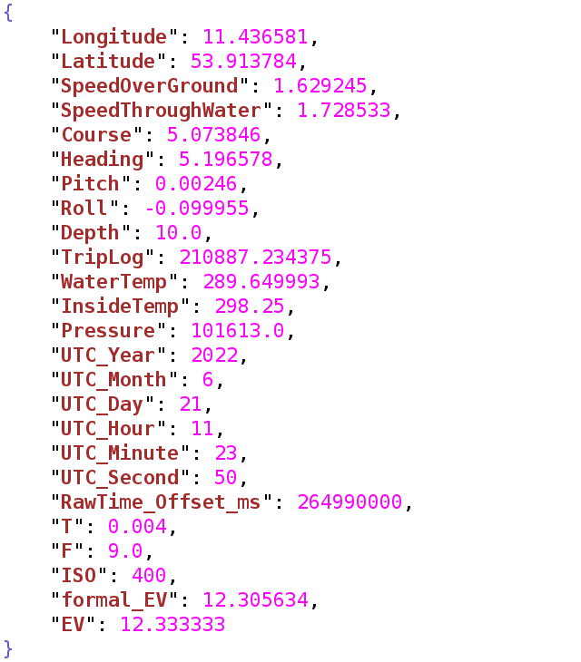
This contains important data for the color grading later on as well as for visualization of various things, rounding up the time lapse in general.
Preprocessing of RAW Images
The RAW images have been piped through darktable (https://www.darktable.org). Two important steps have been carried out here: Denoising (especially important for nightly scenes) and correction of lens vignetting. Actually, there’s also a third important step: Conversion of the image format from a more or less proprietary RAW format into the 32Bit floating point OpenEXR format for further processing. Importance here is that no or at least as possible information is lost for the actual color grading. Challenge here: The size of a single picture is raising to approx. 130MiB. Considering a total amount of 80000 pictures this results in around 10 terabyte of intermediate data.
Color Grading
Although there have been also taken some actions regarding color grading from an artistic point of view, this part of the work flow should be better reflected by the term “deflickering”. The point is that whenever the exposure of the camera has been changed, there will be an abrupt change in the brightness of the picture. This would not be acceptable for a time lapse. Though, for a time lapse a certain amount of flickering is inevitable. For instance when in one picture the sun is shining and in the next not. But there shall be no abrupt changes out-of-the-blue.
So for this process Blender (https://www.blender.org) has been chosen due to its extensive scripting capabilities. A script has been developed here that is reading the exposure information stored within the Json file associated with the particular picture and is correcting the overall exposure value (known as EV) of each picture to a fixed value. Of course, this is either resulting in pitch-black pictures during the night or totally overexposed pictures during the day. So the exposure needs to be re-adjusted with more or less smooth transitions. This is a manual task, but blender is offering useful functionalities here.
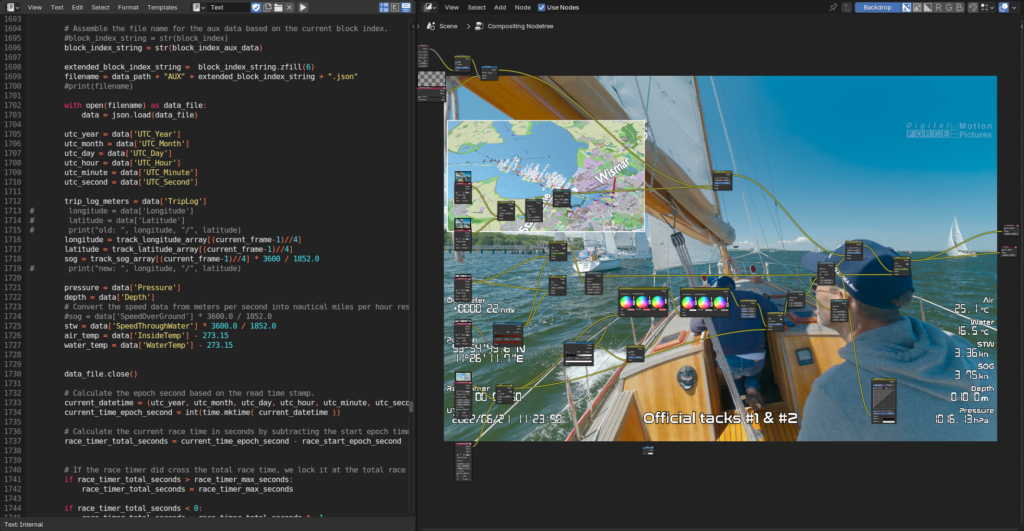
The following picture is merely a demonstrational screenshot from Blender, showing a node setup used for the color grading, backdropped by the very same scene that has been shown above in junction with the autoexposure mechanism. There’s also visible part of the script and the graph for manual exposure value correction.
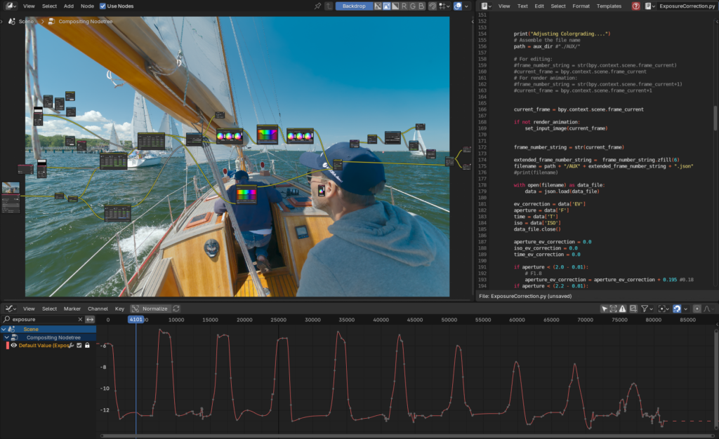
The peaks in the graph mark the night times. As an interesting side effect it is worth noting that the night-corrections are getting weaker and weaker over the time. This is a result of the fact that the boat is moving closer and closer to the northern arctic circle, where the night time during the summer disappears, finally.
All in all this exposure correction did work almost flawlessly with the exception of a few situations during early morning hours that would have required a significantly higher dynamic range of the camera. That is, in the final movie can be seen how the sky is switching over in brightness. Although this is not very nice, it’s not ruining the general appearance.
Btw., watch out for the image quality and detail of the picture shown in the screenshot above, compared to the very same Jpeg-based image of the earlier screenshot. If you are going to make quality-photos, never use Jpeg straight from the camera but do some color grading with your RAW photos! However, for the purpose of a preview it’s ok here.
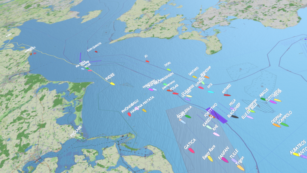
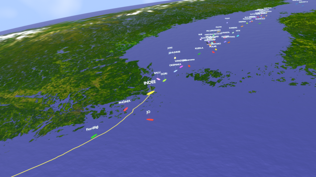
Animations
It has been found useful to add some sort of animations that from time to time are showing the position of the vessel on the map resp. the planet. Since the context of the adventure is a race, it would also be good to add the other race participants here. During the race, all boats had to carry a tracker that is reporting the position through the Iridium satellite system. The trackers are operated by YB Tracking Ltd. (https://www.ybtracking.com). Data for all participants has been provided by YB Tacking through Agora direct MidsummerSail GmbH. In a first instance, this data had to be converted and interpolated down to the 10s time frame of the time lapse from the original 10 minutes. Also there had to be removed several apparent tracking errors from the data.
For the animations themself there has been used again Blender as base. There has been developed an extensive script that is handling a more or less arbitrary number of vessels and places them on the globe depending on time.
The textures for the globe are based on:
- The NASA Blue Marble project (https://visibleearth.nasa.gov/collection/1484/blue-marble), although used only for the intro and the outro where the full planet is visible. Only water mask and elevation data has been used else as well.
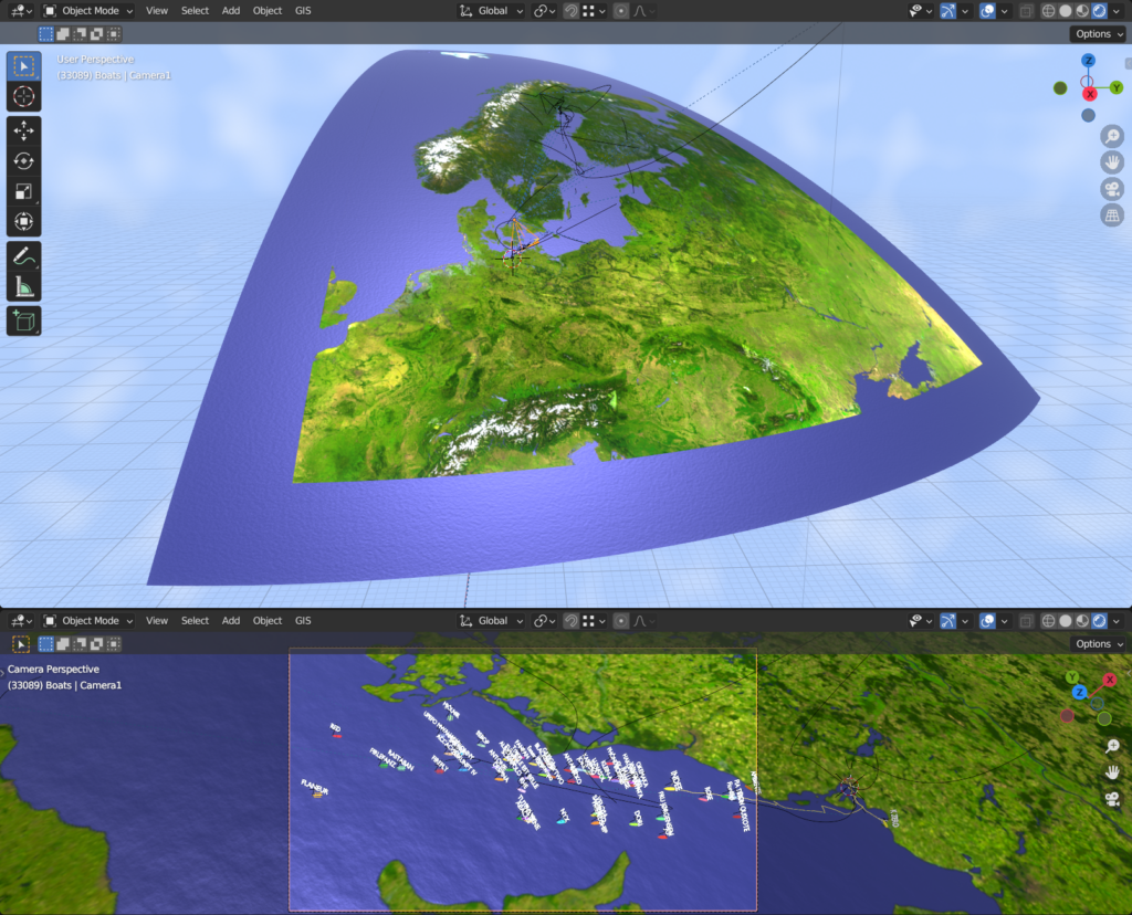
- Unearthed Outdoors True Marble Project, which is providing free Landsat imagery with a resolution of 250m. Unfortunately, Unearthed Outdoors is not existing any more. However, the imagery can be found on the internet. The imagery used here has been partly heavily edited by means of removal of existing clouds, which would have made the overall appearance kind of ugly.The screenshot above is showing one part of the True Marble texture.
- Map data from OpenSeamap (https://www.openseamap.org) resp. OpenStreetmap (https://www.openstreetmap.org). OpenSeamap is based on OpenStreetmap. In order to make use of these maps, they first had to be transformed from their so-called Mercator projection into a so-called Equirectangular projection. The latter one is needed in order to map this data onto a sphere. This transformation has been carried out through Blender as well by mapping the Mercator representation onto a properly curved plane. The details are rather complex here…
Notice that no data from Google Maps resp. Google Earth has been used here, although there’s much better resolution available (at least where land is involved). But the result should be free of potential copyright infringements. Furthermore, the Google Earth data is often associated with abrupt texture changes which is not very beautiful. The best quality from that point of view has definitely the NASA Blue Marble project. However, it has got a rather low resolution and can be hardly used for closer zooms.
Of course, these higher resolutions can only be used fractionally when not showing the complete earth. So there has been also developed a technology that allows for a more or less seamless blending between different planetary textures.
Apart from that there have been integrated some fancy more or less automated attitude adjustment of the vessel names depending on the position of the camera. The camera flights themself had to be manually made – which is a science alone provided that this should leave some sort of a natural impression.
So in the end, there have been created several animations looking like these (still frames):
Because the technology was present anyway, there has also been made a cover of the race as such, which is available here:
Additionally, this video does also contain some extra technology allowing for a seamless dynamic change of the speed of the replay.
Combination of the individual Images into an actual Time Lapse
The intention of the whole project was not to just provide some sort of technical insight about what is going on on the vessel during the course of the race, but also to provide some sort of “epic eye-candy”. Well, a time lapse with a moving camera is highly critical here, as there can be large changes of the scene from picture to picture. In the beginning of that project there have been also general question marks about whether such a movie would be watchable at all by means of human perception. In fact, some people will certainly consider the result as “unwatchable”.
In the end, the problems have been found to be significantly less critical than initially anticipated. This is also because of a blending technology that is blending each picture into the next rather than just switching over pictures. This technology has got it’s limits as well, but is making transitions more smooth. These things are also done through Blender and an according script, that is taking the colorgraded picture feed as input. At the same time, this script is integrating additional information into the pictures resp. the output feed (see next section).
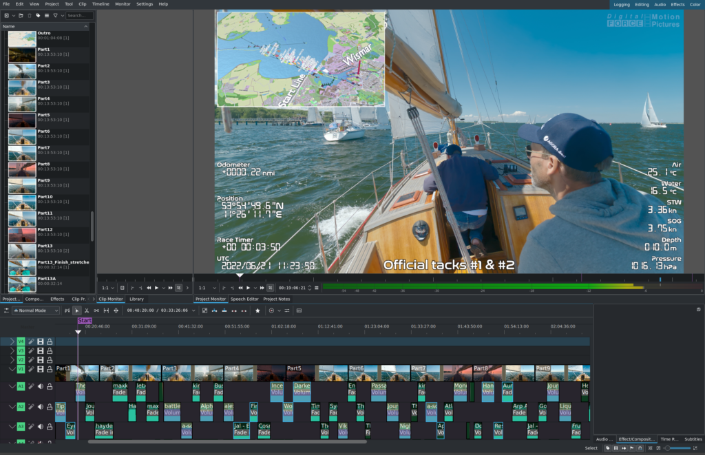
Embedding of additional Information into the Pictures
The final time lapse movie was intended to also show some additional information such as the current speed of the vessel, the current date and time, some comments regarding the current situation, and also some previously mentioned animations illustrating the current position. All these things are also integrated into the pictures using Blender through a script, together with the blending of each single picture into the next one.
Here does also come the aforementioned Json-file into play a second time, which is containing extra information per picture. So the script is reading the according information from the proper file and is overlaying it in form of textual elements over the picture. The same is done with animations, individual pictures or comments, whose position in time can be set within the script in a somewhat convenient way.
It should also be noted that while embedding these additional things into the image there is also applied an optional red-shift of the elements. This is looking like here, for instance:
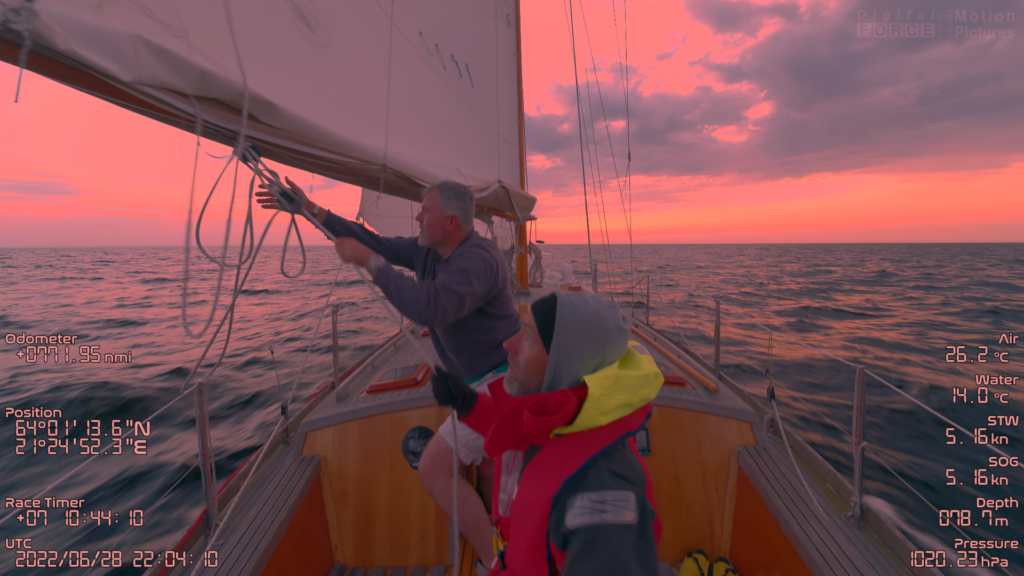
This reddish color is more convenient to the eyes during a generally darker environment – for the same reasons why dim red light in the dark is better than bright white light. The decision when to fade the elements between white and reddish as well as the strength of the reddish taint has to be done manually through some interpolated keyframes.
Btw., this scene is showing the most hairy situation over the course of the race, which is a sheet break of the main sail.
Adding Music
This has been the final step. Technically this has been rather simple and straightforward. A simple linear video editing program has been used here – Kdenlive (https://kdenlive.org). The difficulty here was to select the right music that is representing the current mood and activities suggested by the pictures. The style of the music has been held mostly cinematic and epic, with a few experimental exceptions.
A vast amount (a couple of thousands) of freely available music pieces from various sources has been screened and checked for their possible integration. In the end, around 70 pieces have been finally used for the sound track of the totally three hours the movie took in the end (although a few pieces have been used more than once). Some of the music pieces had to be slightly modified as well in order to fit into the project. I.e. they have been cut or looped.
That’s all
More or less…
Conclusions
All in all there has been achieved a result that is far beyond of what has been initially anticipated. The question whether it was worth to go that way is difficult to answer, as it is in many cases. The amount of work has been completely underestimated at the time there has been made the decision to enter that project and accept that challenge. Of course, this does not refer to the decision to participate at that race as such, which is a different matter. The latter is just “biting the teeth together” for 3-4 weeks and hoping that you are not hit by major technical failures resp. hoping that you are able to deal with the mishaps that will hit you anyway. [3-4 weeks because the vessel needs to be brought back again – and the trip back has been way harder here….]
So the majority of time that has been spent on that project is not so much dedicated to the production of the movie as such, but merely dedicated to the development of the technologies and tools that have been needed for the production.
The full time lapse movie has been also aired by the German broadcasting stations h1 (http://www.h-eins.tv) and ALEX Berlin (https://alex-berlin.de) in August resp. September 2023.
There are some plans to reuse large parts of the technology that evolved from that project within another similar project that is dealing with a multi-day time lapse including a moving camera as well. Future will show whether this becomes realized.