In Chemnitz we have a planetarium for educational purposes (Schulplanetarium Chemnitz). The planetarium hardware itself is a rather old Carl Zeiss Jena ZKP2 model. This planetarium is more or less completely manually controlled. It provides control panels with various switches and potentiometers which control things like lamps and speed of motors.
The goal of this project was the development of a small interface that allows to control some of the planetarium functions through a computer. Of course, the purpose of this is not just to press a “virtual” button or adjust a “virtual” potentiometer instead of manipulating the real controls. Rather it is intended in order to prepare complete sequences in advance to a presentation. So the demonstrator has his hands more free during a presentation.
Computer Interface:
If all this control stuff would have been built from scratch, the best solution would probably be to use one (or a few) micro controllers that are controlled by the host computer via a standard RS232 interface. So one would send commands to this micro controller that change the state of a switch function or the speed of a motor.
However, that would require to write a corresponding piece of software for the host computer. Writing some simple graphical front-end would not be a big deal, actually. More complicated is an appropriate sequence flow control. But the problem is that it would be some stand-alone solution.
At the Schulplanetarium Chemnitz is already a system in use that appears to be a de-facto standard system for audio-visual control systems. This system is provided by the Swedish company Dataton. One subsystem is the so-called ANALOG SMARTLINK. It provides 32 analog channels that have a voltage range of 0V – 10V (12Bit resolution). There is also a sophisticated software that allows the generation of complex sequences. So it was a natural conclusion to use the analog channels as a basis and the planetarium control can be nicely integrated into the system that is already in use for other things (such as additional projectors).
Apart from the Dataton ANALOG SMARTLINK system it should be no problem to attach almost every other DA-converter system – provided that it has an output range of 0V – 10V.
Planetarium Interface:
The planetarium is being manipulated by the control interface directly at the control panels. That is, switches and potentiometers can be bypassed by this control interface. The advantage of this strategy is that the manual controls remain intact and can be used in parallel to the computer control.
The fact that the interface connects to the control panels also makes it very easy to integrate into the ZKP2 system. The only thing that has to be done is to solder a bunch of wires to the planetariums’ control panels.
The actual Interface Hardware:
The hardware is more or less completely analog (i.e. without any micro controller etc.).
All analog channels coming from the ANALOG SMARTLINK are isolated from the planetariums’ electrical circuit using opto couplers. That provides a good protection of the Digital-to-Analog conversion hardware for the case of some “events” inside the planetarium.
Switch Control
The switch functions are implemented rather conventional using Reed-Relays. A relays can be activated with a high analog voltage and deactivated by applying a low analog voltage. There’s also an hysteresis implemented that avoids oscillation of the relays in case of critical analog levels.
The interface can handle a total of 14 selected switch functions.
Motor Control
Controlling motor speed is not done by applying a desired voltage to the motor (as done normally via the potentiometers), but by driving them in a pulse-width-modulation scheme (PWM). MOSFETs are used as switching devices. The higher the analog voltage the longer is the pulse width and the faster is the motor speed.
There were some difficulties with a few motors that are bidirectional and require to switch either +12V or -12V (the use of an H-bridge was not an option there).
Five selected motors can be controlled by this interface.
As an additional feature, a threshold can be set for each motor individually. It can be used to prevent the motors from being operated in an illegal state (i.e. too short impulses that are insufficient to get the motor rotating).
Possible Insufficiencies:
When treated just as a manual control panel replacement, there will appear basically no problems or changes in behavior compared to conventional manual control.
As for the switch functions, there is no question at all in any case.
The behavior of the motor controls is not completely linear. That is, the motor speed does not scale linearly with analog voltages from 0V to 10V. In fact, the motors start rotating at around 4-5V. (Note: A design that stretches the usable range from 0V to 10V with an ultra-linear behavior would be well possible, but it requires more active circuitry and more expensive opto couplers.)
But that’s actually not an issue. What appears to become a potential problem is repeatability. The motors inside the planetarium are neither stepper motors, nor does the planetarium return positional information to be evaluated in order to implement a closed-loop control with feed-back information.
The only information given is the final projection. That is, when the demonstrator wants to have a certain element at a certain position, he manipulates the appropriate potentiometer until the element has its desired position. So to speak, it is the human being that closes the loop (eye-brain-hand).
When playing back complete sequences via control of a computer, the demonstrator has to hope that an object on the sky moves always for the same angle given a certain motor speed and motor activation time. Whether this hope can be fulfilled depends on the quality of the motors and mechanics inside the planetarium, finally.
Practice will show to what extend these potential problems attribute to the handling.
Some Pictures:
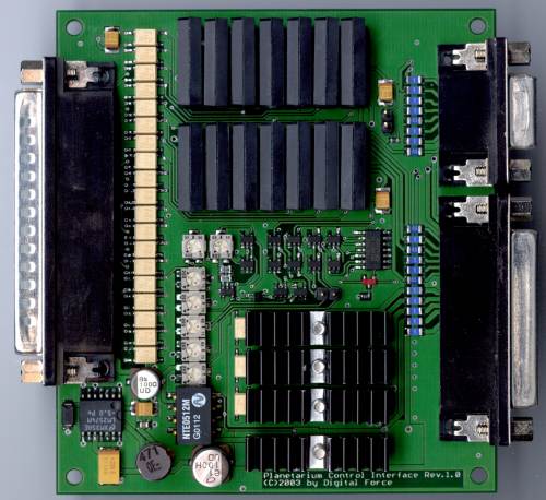
The following picture shows the top side of the board.

At the left side is the 37-position SUB-D connector for the Dataton ANALOG SMARTLINK. Clearly visible is the bank of opto couplers right next to this connector.
At the right side there are two connectors that connect the interface to the planetarium. Left to these connectors are some small fuses visible (blue parts). These are intended in order to provide protection for the case of wrong installation.
The Reed-Relays can be found at the upper part of the board.
The radiators that can be seen cover the MOSFETs that are used for the motor control. Because the motors inside the planetarium do not draw a vast amount of current (currents are in hundreads of milliamperes area), MOSFET heating is not very high. The radiators are mounted nevertheless for safety reasons.
The circuitry in the middle of the board is the actual motor PWM circuitry. The PWM signals that are used for switching the MOSFETs are generated there.
At the lower left corner some voltage regulation circuitry can be seen that derives the supply voltage from the planetariums’ power rail. Modern switching-mode regulator technology is used here instead of old and power-wasting linear regulators.
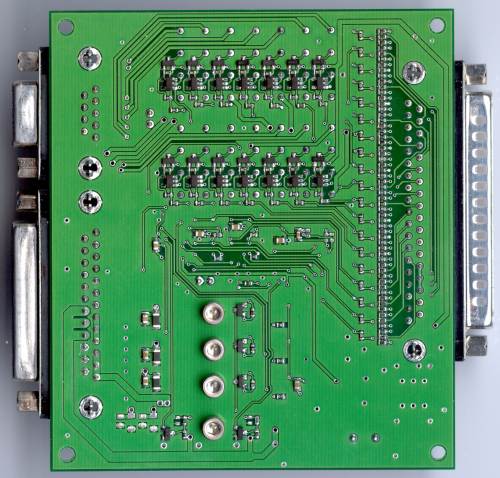
The next picture shows the board from the bottom side.

There’s not much left on this side. The most important parts are these visible in the upper area. This circuitry drives the Reed-Relays.
Reproduction
It is possible to manufacture copies of this control interface. But note that it is not a commercial product. So far, there’s also no case available.
I’ve also written an extensive 60-page technical documentation and user manual that I can provide together with the PCB layout under certain conditions. So if you are interested, drop me an Email: Mario.Trams@digital-force.net