Well, not really a project, but something that might be interesting for the one or the other. This is showing how to:
- Add a socket to be able to attach an external antenna to the RaspberryPi 4B
- Increase the USB Power output capability of the RaspberryPi 4B form 1.2A to 1.7A
How to add a Socket for an external WiFi Antenna
The RaspberryPi has got an integrated antenna on it’s PCB that is fine for most applications. However, there are some reasons why one might want to use a different antenna. Two popular reasons are:
- Using a better antenna with increased range.
- The RaspberryPi is being enclosed in some metal casing where the integrated antenna would not be working at all.
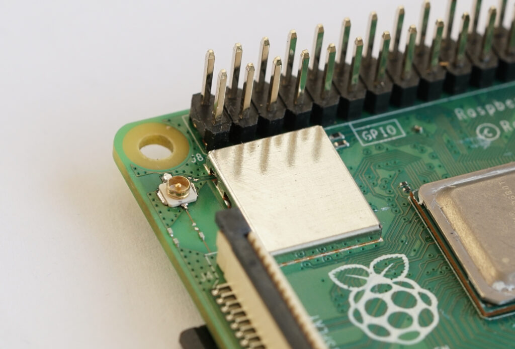
For reasons not known to me, the designers of the RaspberryPi 4B did not really add a provision to be able to use an external antenna. If you look at the upper/left corner close to the 40pin-header and the mounting hole, you will find a solder-pad. It seems that this is or was meant to be used for attaching a small antenna socket. In fact, there are several tutorials available that make use of that pad. However, the problem is that this is placing the antenna socket extremely close to the mounting area, so that it is hardly possible to use that mounting hole any more. Even more worse, there are some casings or aluminum constructions for cooling purposes that cannot be used at all without larger modification.
Another important point is that an antenna socket is not just to be added “somehow”, but it must or should be also as stable as possible so that it is not being simply ripped off from the PCB during plugging/unplugging the antenna cable.
Important: It is not possible to use both external and integrated antennas and the integrated antenna by means of a fallback-antenna! When you are going to use an external antenna, you need to waive off the integrated antenna. That is, the integrated antenna won’t work any longer and you MUST use an external antenna from then on. So think carefully about what you really need! Though, you can also revert back to the integrated antenna. But that requires additional work again.
What parts and equipment do you need?
- A so-called MHF-I socket, sometimes also referred to as “I-PEX MHF-I”. Examples are Samtec RSP-122811-01 or Delock 65892. If you order them, order a couple ones because they are easily damaged for instance by soldering them too hot or too long!
- A sharp knife (typical “cutter-knife”).
- A soldering iron – not too weak but also not too hot (perhaps 16-25W). Ideally you have two of them.
- At least a magnification glass – the more professional the better. Best is a technical microscope. Warning: Without at least some sort of magnification glass you can immediately forget about that project, because you will probably be lost! That’s not a joke!!!
- Of course a suitable antenna and/or antenna cable with a plug mating with the MHF-I socket.
Step 1: Create SMD Pads
The first step is to create some sort of pads where the antenna socket can soldered later on. A knife is being used to scratch away the green solder stop from the PCB. Apply just a gentle force onto the knife. You must just remove the solder stop – not the copper! In the end this is looking as follows:
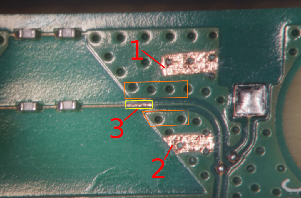
Be specifically careful when removing the solder stop from the central wire which is the actual antenna wire. This wire is very thin and can be easily destroyed. Furthermore you must not remove any solder stop from the areas marked orange. The solder stop there is important because the MHF-I socket is not really suitable here and can easily make a shortcut between the antenna wire and the areal ground copper. The green solder stop acts as isolation here. In case it is destroyed, it needs to be restored again somehow….
Step 2: Apply Tin to the Pads
Now apply some tin to the created pads. There must not be “mountains” of tin – just enough to have a thin layer of tin. If there’s too much, then there will be troubles soldering the socket.
Step 3: Solder the MHF-I Socket
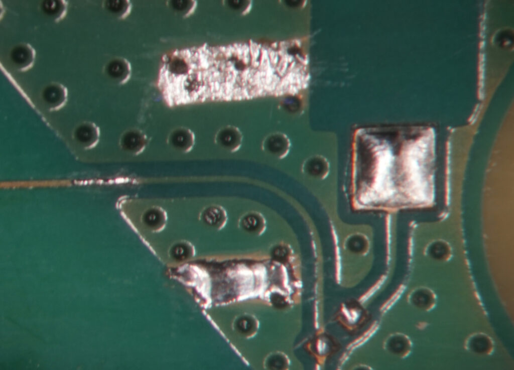
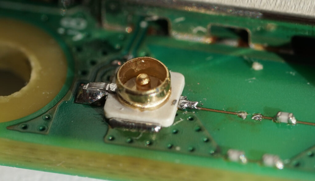
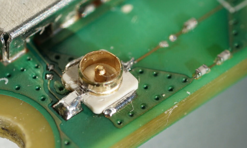
Now the socket can be soldered. Take care for the proper alignment. The contact of the socket that connects to the center pin of the socket needs to be soldered to the thin antenna wire. Notice that it would be formally better when the contacts of the socket would be tinned from the bottom side before soldering them. However, this turned out to be very difficult and the socket can be destroyed easily due to overheating. So it is better to not do this and use some soldering flux during the soldering process. The soldering iron should be attached a bit longer to the larger pads until the tin is flowing well. The result should look similar to this:
There is also a fourth contact on the antenna socket that is directly connected to the outer shell of the socket and automatically connects to the larger pads as well. For enhanced stability this can be soldered to this “official” antenna pad. This is not connected to the antenna wire anyway (you see the open bridge in the picture…). When soldering this position, take care that not too much of tin is flowing into the direction of the outer shell of the antenna socket! Else you might get into troubles plugging the antenna cable.
Step 4: Deactivate the integrated Antenna
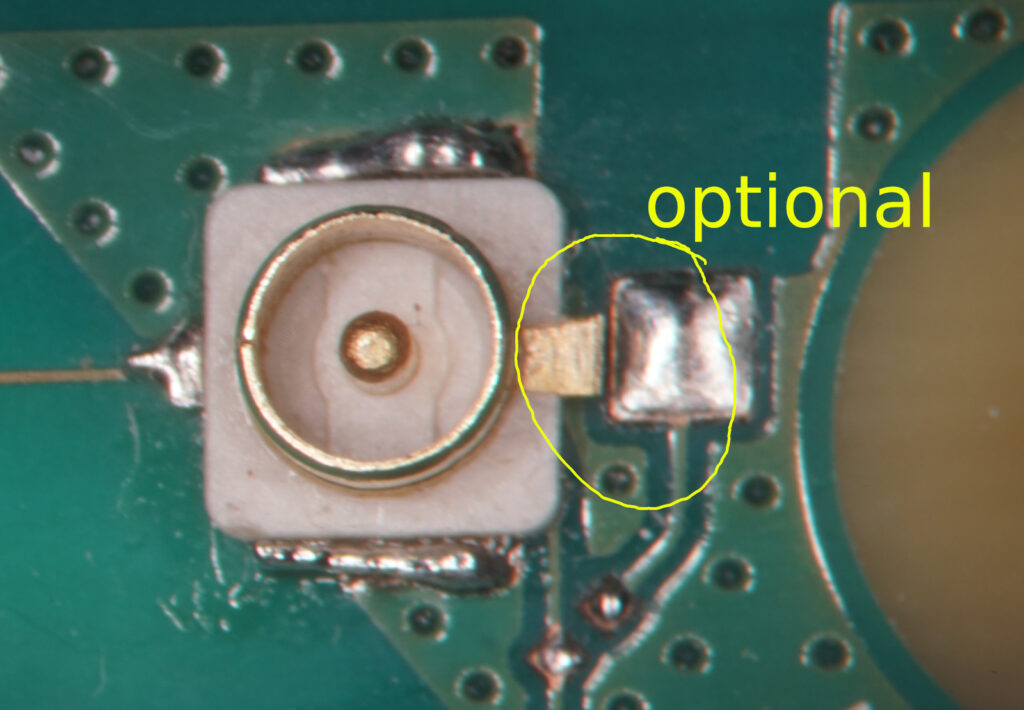
Finally the PCB-antenna needs to be disabled. The most non-destructive way to to that is to remove the small capacitor in the antenna wire next to the socket:
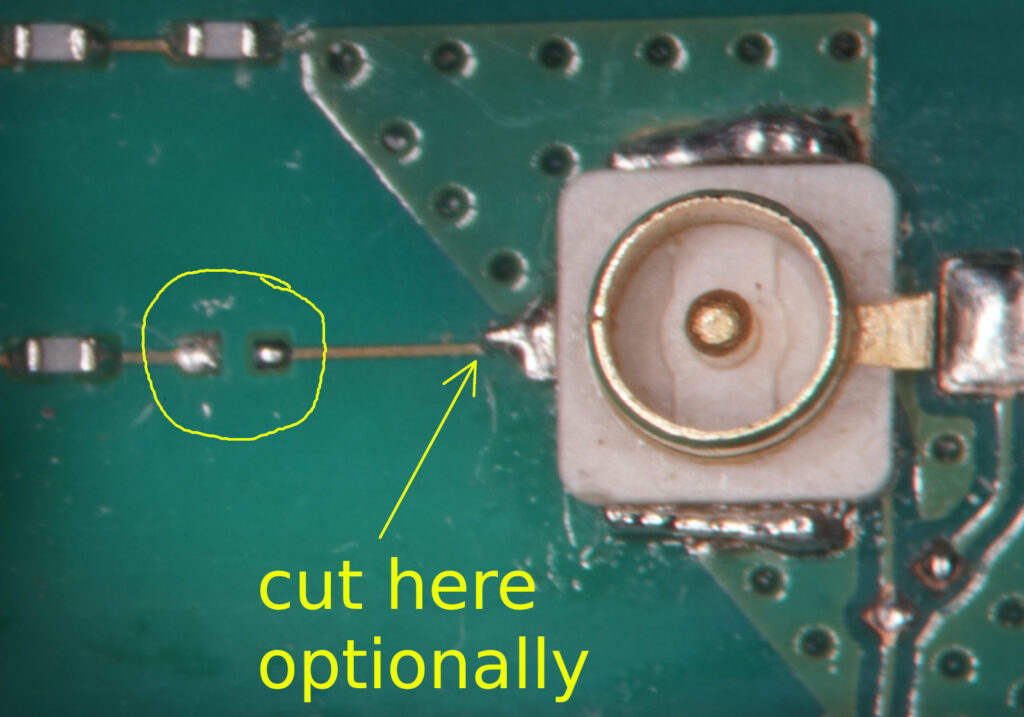
Ideally, the capacitor can be removed by using two soldering irons. Removing the capacitor is not optimal, however. The point is that there is left a stub that is disturbing the function of the antenna. So optionally you might cut the wire as shown in the picture instead. I did not cut the wire and left it as shown. The results did appear to be more than satisfying that way. I did not make an analysis of what quantitative use it is to cut the wire. From a formal point of view this positioning of the socket is not optimal anyway even though this short stub is being removed. Ideally, the socket would have to be rotated so that the antenna wire is ending straight into the center pin of the socket. However, considering aspects of mechanical stability this does not seem useful here.
The final result
Now you can hook up a proper antenna with a proper connector and WiFi should operate normally resp. hopefully better than before.
As a final note: Keep in mind that these MHF-I connections are not meant to be regularly plugged and unplugged. They have a very limited number of mating cycles. I read about 30 cycles in some data sheet. So you should unplug and plug an antenna cable only when it is really needed!
How to increase the Output Power of the USB sockets
A few important words in advance: The RaspberryPi 4B is limiting the output power on the USB ports not by means of a “chicane” but by means of protecting itself from a crash. If there is drawn too much power from an USB device, the USB devices will be crashing, but not the computer itself. This is specially important when the RaspberryPi is being supplied through its USB power connector. So as a general hint:
Do this only in case you supply power through the 40pin header and also ensure that you can provide enough power from there!
It is said that the RaspberryPi 4B can supply up to 1.2A for all USB ports. I did make some sort of reverse-engineering and found that the power for the USB ports is provided through the 6-pin device that is located close to the USB 2.0 ports:
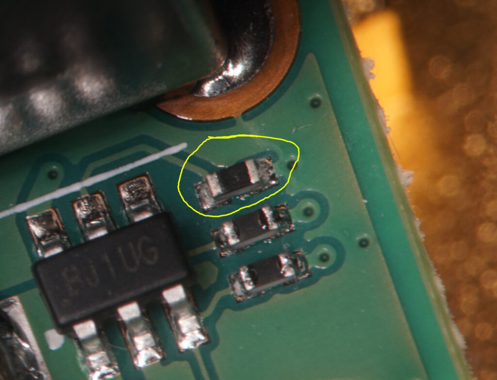
It is not completely clear, but this 6-pin device is probably a Texas Instruments TPS2553 or compatible device: https://www.ti.com/product/TPS2553 This is a current-limiter with an adjustable current limit up to 1.7A. The current limit is being set with a resistor. This resistor is the one marked in the picture above. The value of that resistor is originally 19.6kOhm. This is setting the current limit to something a little bit above 1.2A. The smallest officially allowed resistor as per data sheet of the TPS2553 would be 15kOhm, which is resulting in a current limit of 1.7A. So when you remove that resistor and put a 15kOhm one instead, the formal current limit is being risen from 1.2A to 1.7A.
The resistor is in SMD 0402 form factor. It is also possible to solder a larger SMD 0603 form factor there, but you need to take some more care.
What if you need more than 1.7A?
Well, you might use a resistor smaller than 15kOhm. However, this is not recommended as per TPS2553 data sheet. Alternatively you might bypass the TPS2553 by directly connecting the 5V rail of the RaspberryPi to the USB ports. Although I did not test this, this should be working as well. However, notice that in that case you will definitely crash your RaspberryPi in case there is some huge power consumption on the USB side. In case there is a short cut, you might also burn up some cables or wires on the PCB. So this is certainly not recommended and only a very last option.
More Improvements for the USB Power
When having a closer look at the powering of the USB ports it turns out that this is not made very well. First of all, it is not good practice to power all USB ports through that single current limiter. This is because an overcurrent-situation on one port can kill the other ports as well. However, this practice is a tribute to simplicity and last but not least the price. Nonetheless there is missing an important component: The USB specification requires a larger capacitor at the power rail of each USB port – at least 120uF in particular. The RaspberryPi 4B apparently does not have a single Microfarad here. The capacitor is required resp. makes sense especially to deal with hotplugging situations where a new USB device is being attached during runtime. In this moment there can be drawn substantially large amounts of current. In case of the original RaspberryPi 4B setup without any capacitor directly at the USB ports, this is in turn leading to a high current through the current limiter. This might further lead to a shutdown of the current limiter and hence a failing startup of the attached USB device.
In order to improve that situation it might be an option to solder some capacitor with a couple of hundreds Microfarads close to the USB connectors resp. directly to their power pins. However, this is not very practicable and does also depend on the available space on the bottom side of the PCB. What I did in order to improve that situation somewhat is that I took some USB cable with an USB-A plug, cut away the cable from the plug so that I’ve got the plug with a few millimeters of cable, and then soldered an electrolytic capacitor with 330uF and a voltage rating of 16V to the cable. Don’t use voltage ratings below 16V here as there can easily appear voltage spikes of 10V during hotplugging! So this is giving me a “removable capacitor” that I can plug into a USB port that is not being used else (provided there is a free one available….). This is certainly not optimal, but better than nothing.
Note: The capacitor attached to the USB power line must not be too large and it should also be an electrolytic one with a larger ESR (Equivalent Series Resistance). When it is too large and has got a very small ESR, then it would provide a certainly good stabilization during hotplug-events. However, on the other hand it might easily knock out the current limiter during initial power-up.